Goals
- Use the OV7670 digital camera and an FPGA to detect and distinguish colored shapes.
Arduino Camera Communication:
Every time the camera books it must have the correct registers written to it through its SCCB bus. We mimic this bus using the arduino I2C bus and Wire library, alongside the lab provided code. We begin by resetting the bus through a write of 0x80 to register 0x12. After waiting for this to finish we proceed to write the registers with the values listed above, as well as setting the color matrix. Finally, we read each written register and check it against the expected value.

Arduino FPGA Communication:
In order to communicate the existence, shape, and color of a particular color in the maze we implemented an R2R ladder with R= 500 ohms to act as a simple digital to analog converter. We then fed this analog signal to an analog input pin. This was in order to minimize the number of pins required on the Arduino side. We used the MSB to represent color, and used the two less significant bits to represent shape. We defined 000 as representing “no shape”.

Click here to see full code for this part
Setting up the FPGA
PLL and setup
We started by setting up the Phase-locked loop (PLL) with clocks of frequencies 24, 25 and 50Mhz, to avoid undesirable effects of clock skew. This was done using the ALTPLL function inside Quartus’ IP Catalog Library. The 24Mhz clock was used to drive the camera’s MCLK, the 25MHz clock drove the VGA module and to read from the M9K module, and the 50MHz clock was used as writing rate to the M9K module. We were supposed to use the 25MHz clock to drive the image processor, but we ended up not using that module as you will see below.
sweetPLL	sweetPLL_inst (
	.inclk0 ( CLOCK_50 ),
	.c0 ( PLL_24 ),
	.c1 ( PLL_25 ),
	.c2 ( PLL_50 )
	);
We chose different values for reading and writing from/to the M9K module because, as the lab description indicates, we can’t read and write from the same memory address at the same time. We chose to write faster than we read because that way we could avoid reading garbage, or empty addresses.
We also chose to keep the pre-established 176x144 resolution, taking into consideration the energy, time and memory costs of computing larger frames.
Warning! If you’re using Quartus in your personal computer, make sure you have installed the Cyclone IV support files. Our computer only had the Cyclone V family installed and didn’t have the ALTPLL function. Also, the USB blaster will constantly uninstall (at least in Windows), but you can manually reinstall the drivers by opening the Control Panel --> Devices and Printers --> USB Blaster, and manually search the drivers in the folder where Quartus is installed.
Showing the Russian flag
Having finished the setup, it was time to test our buffer reader, to make sure that the information exchange between the M9K and the VGA modules was seamless. We decided to attempt printing the Russian flag. We did so by dividing the 176x144 window into 3 equal stacked rectangles colored white, blue and red from top to bottom. We used the following Verilog code:
always @ (posedge CLOCK_50) begin
		if(WRITE_ADDRESS <= 15'd8448) begin
				pixel_data_RGB332 <= WHITE;
		end
		else if(WRITE_ADDRESS > 15'd8448 && WRITE_ADDRESS <= 15'd16896) begin
				pixel_data_RGB332 <= BLUE;
		end
		else begin
				pixel_data_RGB332 <= RED;
		end
end
Here’s the result:
Downsampling
Warning! This one was a pain and took the longest time, so beware.
After we verified the buffer reader was working correctly, we started building the downsampler. We need to downsample because the camera outputs pixel color information in several formats, but we are using RGB332 because our RAM can only store 8 bits per pixel. We decided to configure the camera to relay pixel color information in the format RGB565, which sends 16 bits of information over 2 clock cycles (8 bits each). The manual says it sends 5 bits of red and 3 bits of green during the first cycle, and the other 3 bits of green along with the 5 bits of blue during the second.
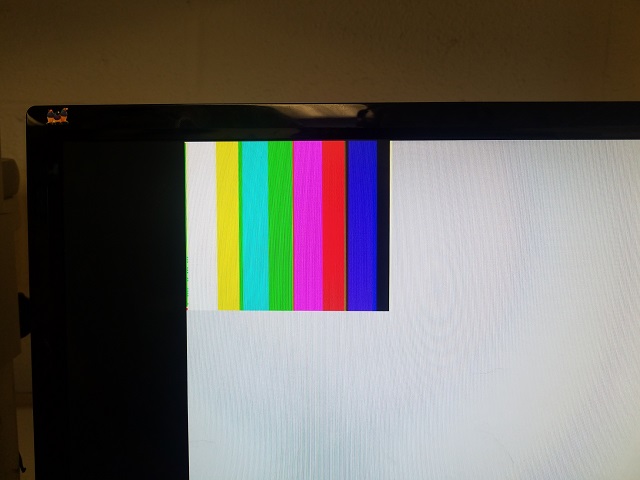
Considering this configuration we decided we should take the most significant bits of each color to create our RGB332 pixel color byte. We put together code to capture the 3 most significant bits out of the 5 representing red color and the 3 bits of green available on the first cycle, and only take the 2 most significant bits of blue out of the second cycle. To ensure we were reading the values only when data was valid, we used PCLK (pixel clock), and tracked when we moved from one pixel to the next, when we advance a row, and when we moved to a new frame. However, when we tried the color bar test our colors were off.
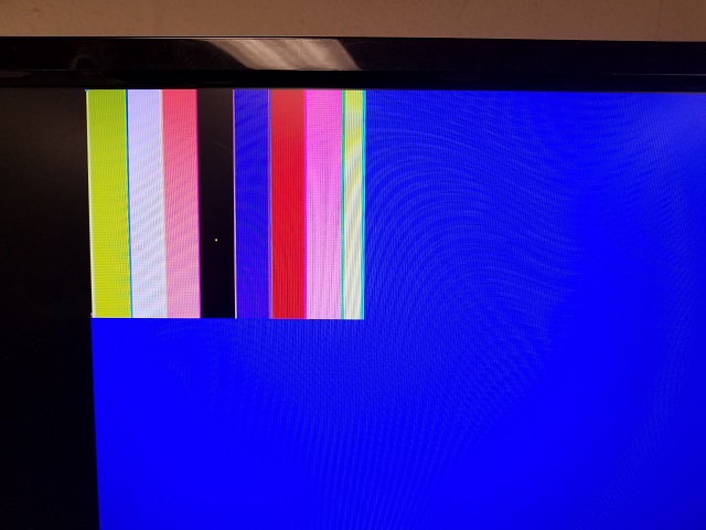
We started researching, and collaborating with other teams that were having similar issues. Team 8 helped us realize that for some obscure reason, the camera was sending the green/blue bits on the first cycle, and the red/green on the second. We proceeded to invert the sampling order, and got much better results, which can be seen below. The downsampling code can be found in the color detection section below, since we did our image processing within that same code section.
Warning! Note that the pin out of GPIO1 in the DE0-Nano board is rotated 180º in comparison to the pin out shown in the user manual. The ground pins are actually on the set of pins that’s closest to the edge of the board.
Color Detection
We decided to not use the image processor module given, and instead process pixel color information in the downsampler, as soon as it is received from the camera. Our approach consisted of blue and red pixel color counters that incremented whenever a pixel was dominantly blue or red. When we reached a full frame, namely when VSYNC is 1, we checked if there was a predominant color in the frame by comparing the blue and red pixel counters. We also made sure the counters surpassed a threshold, which means they also covered a significant portion of the frame, to minimize false detections in noisy images.
We created a 3-bits register to relay information about shape and color to the Arduino, cleverly named shape_n_color. We decided to make it 3 bits because the day of the competition we will be detecting 3 shapes: triangles, squares and diamonds, and 2 colors each, which makes 6 different combinations. We must also be able to relay when we detect nothing, so there are 7 possibilities in total. 3 bits allow us to distinguish up to 8 possibilities.
// I/O for img processor
assign GPIO_0_D[28] = shape_n_color[2];
assign GPIO_0_D[30] = shape_n_color[1];
assign GPIO_0_D[32] = shape_n_color[0];
For this lab we were only interested in detecting the color, so we assigned arbitrary shapes. More details about this are provided in the Arduino FPGA Communication section above. Find below the code for the downsampler including color detection functionality:
always @ (posedge PCLK) begin

	if(VSYNC && !VSYNCprev) begin
		Y_ADDR <= 0;
		X_ADDR <= 0;
		flag <= 0;
		W_EN <= 0;
		pixel_data_RGB332[7:0] <= 0;

		// Image processor
		if ((blue_px > red_px) && (blue_px > px_threshold)) begin
			background <= BLUE;
			shape_n_color <= 3'b101;
		end
		else if ((blue_px < red_px) && (red_px > px_threshold)) begin
			background <= RED;
			shape_n_color <= 3'b001;
		end
		else begin
			background <= GREEN; // detects nothing
			shape_n_color <= 3'b000;
		end
		red_px <= 0; // resets red pixel counter when it is at a new frame
		blue_px <= 0; // resets blue pixel counter when it is at a new frame

	end

	else if (!HREF && HREFprev) begin
		X_ADDR <= 0;
		Y_ADDR <= Y_ADDR + 1;
		flag <= 0;
		W_EN <= 0;
		pixel_data_RGB332[7:0] <= 0;
	end
	else begin
		Y_ADDR = Y_ADDR;
		if (!flag && HREF) begin
			flag = 1'b1;
			W_EN = 0;
			X_ADDR = X_ADDR;
			pixel_data_RGB332[1:0] = {GPIO_1_D[12], GPIO_1_D[11]};
		end
		else if (flag && HREF) begin
			pixel_data_RGB332[7:5] = {GPIO_1_D[15], GPIO_1_D[14], GPIO_1_D[13]};
			pixel_data_RGB332[4:2] = {GPIO_1_D[10], GPIO_1_D[9], GPIO_1_D[8]};
			flag = 1'b0;
			W_EN = 1;
			X_ADDR = X_ADDR + 1'b1;

			// Pixel color counters
			if ((pixel_data_RGB332[1:0] >= b_blue_threshold) && (pixel_data_RGB332[7:5] < b_red_threshold) && (pixel_data_RGB332[4:2] < b_green_threshold)) begin
				blue_px <= blue_px + 1;
			end
			else if ((pixel_data_RGB332[1:0] < r_blue_threshold) && (pixel_data_RGB332[7:5] >= r_red_threshold) && (pixel_data_RGB332[4:2] < r_green_threshold)) begin
				red_px <= red_px + 1;
			end

		end
		else begin
			X_ADDR = 0;
		end
	end
	VSYNCprev = VSYNC;
	HREFprev = HREF;
end
Click here to see full code for this part
We integrated this with the code written in Arduino to display color detection successfully, as seen in the video below. Please note that we also modified the code to show the background color outside of the 176x144 window to be green when there is no red or blue predominance, and turn red or blue if either is predominant in the frame.