Goals
- Implement IR sensors to detect lines with Arduino.
- Implement line following algorithm.
- Implement “grid shapes” algorithm.
Line Detection
We used the provided QRE1113 IR sensors with digital output. These sensors work by us first sending a digital pulse to the output. We then set that same pin to be an input, and time how long it takes to drop back down to logical zero. This is directly proportional to the amount of light the sensor is receiving. We then sample this into an array and convert that data into a one or zero, depending on a threshold.
long readQD(int pin) { //read from IR sensor
  pinMode( pin, OUTPUT );
  digitalWrite( pin, HIGH );
  delayMicroseconds(10);
  pinMode(pin, INPUT);

  long time = micros();

  while (digitalRead(pin) == HIGH && ((micros() - time) < 3000));
  return (micros() - time);
}

void read_line() {
  for (int i = 0; i < 5; i++) {
	line_sens_data_time[i] = readQD(line_sens_pin[i]);
  }
}

void conv_to_digi() {
  for (int i = 0; i < 5; i++) {
	line_sens_data_digi[i] = (line_sens_data_time[i] < threshold);
  }
}
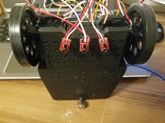
In terms of sensor placement, we chose to place 3 sensors in the front of our robot (one in the center, and two on the sides separated at a distance slightly wider than the tape), aligned with the axis of rotation of the servomotors. This allows us to turn in place around the center senor, and makes the line tracing algorithm far more robust.
Line Following
We implemented the line following algorithm as follows. If the line is detected on the left side of the robot, our detect_foward_direction function instructs follow_line to move left. If it is detected on the right, it instructs to move right. If its detected in the center, it says to go straight.
int detect_forward_direct() {
  if (line_sens_data_digi[2]) { //line on right side
	return 1;
  }
  else if (line_sens_data_digi[0]) { //line on left side
	return -1;
  }
  else if (line_sens_data_digi[1]) { //line in middle
	return 0;
  }
}

void follow_line() {
  last_result = detect_forward_direct();
  switch (last_result) {
	case 0:
  	move_forward();
  	break;
	case -1:
  	move_left();
  	break;

	case 1:
  	move_right();
  	break;

	default: break;
  }
}
Square Figure
Before implementing the algorithm to traverse an eight figure path, we designed an easier test which makes our robot move in a square figure. We added an additional strip of white tape that divided the square, to start testing corner detection. In this figure, there are two different types of corner: formed by 2 or 3 tapes. The algorithm was designed to pass 3-tape corners, and turn in the real corner (2-tape). See video below.
Corner detection and 8-Figure
Since we aligned our sensors with the axis of rotation of the servo motors, we were able to detect the intersection of two lines by watching when all sensors detected white simultaneously, using the code below:
bool detect_corner() {
  return line_sens_data_digi[0] && line_sens_data_digi[1] && line_sens_data_digi[2];
}
We then created an array of instructions for what to do at a corner in an array called ‘directions’. The three possible instructions are move straight, or turn either direction. Every time the robot reaches a corner this array is checked and incremented. Thus, by correctly filling this array we can cause the robot to form a figure 8, or any basic shape.
void start() {
  if (detect_corner()) {
	int current_dir = directions[counter];
	if (current_dir == 0)
	{
  	move_forward();
  	delay(200);
	}
	else if (current_dir == 1) {
  	turn_right();
	}
	else if (current_dir == -1) {
  	turn_left();
	}
	counter++;
	if (counter == dir_length) counter = 0;
  }
  else {
	follow_line();
  }
}
Et voilà: