Goals
- Traverse a maze using proximity sensors to detect walls (or absence thereof).
- Avoid collisions with other robots.
- Prove that it does the previous tasks while performing line following.
Wall Detection (with line following)
We used the provided SHARP IR sensors provided. We proceeded to test the range of the sensors by connecting them to an analog input in the Arduino, and placing pieces of white cardboard in front of them.
After checking the sensor worked properly, we proceeded to check the magnitude reading of the sensor at different distances, so that we could set a threshold.
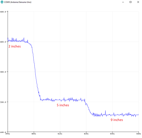
This graph allowed us to set an approximate threshold of magnitude 200. That is, when the robot gets to a corner, the threshold should be low enough that the reading of the sensors will exceed it if there is a wall, and trigger the appropriate action.
Two proximity sensors were used for wall-following. We placed one in the front and one in the right. We implemented the following logic to navigate the maze following the walls:
when the robot is at a corner:
	if (there is a wall in the right && nothing in the front) go forward;
	if (there is a wall in the right && a wall in the front) turn left;
	if (there is no wall in the right) turn right;
We used an LED strip to display when the different sensors detect something. The videos show this more clearly. I.e. when the robot detects a wall on its right, a green LED turns on; when it detects a corner, a red LED turns on; when it detects walls both in front and right, a different red LED turns on.
Robot Detection and collision avoidance
The IR detection is thoroughly explained in Lab 2. We added code to signal when the robot has detected the IR hat (simulation of other robot, placed at approximately 5.5 inches above ground) using the LED strip, and instruct the robot to avoid the collision. In our case, we decided that the best course of action was to stop wherever it detects the IR signal, and resume motion once it doesn't detect it.
The portion of the code that takes care of this will be added to the following section.
It all comes together here
We put all the code together, buckled up, and here are the results:
The code
void setup() {
  sampling_period_us = round(1000000 * (1.0 / samplingFrequency));
  sbi(ADCSRA, ADPS2) ;
  cbi(ADCSRA, ADPS1) ;
  cbi(ADCSRA, ADPS0) ;
  Serial.begin(115200);
  enable_motor();
  strip.begin();
  strip.show();
}

void loop() {
  if (enabled) {
    for (int i = 0; i < 50; i++) {
      read_line();
      //print_visualizer();
      find_direction();
      start();
    }
  }
  else {
    stop_motors();

  }
  sample();
  int f = compute();
  int mag = vReal[(int)(f * samples / samplingFrequency)]; //find the magnitude of dominant frequency
  enabled = !(mag > 14000 && f > 6000 && f < 12000);
  Serial.print("f ");
  Serial.println(f);
  Serial.print("mag ");
  Serial.println(mag);
}
(...)
Click here to see full code for this part